ITALVIBRAS
71
N
3.76
4.50
MVB 1510/15
I
476
290
171
250
17
6
278
46
20
35
71
71
M25x1,5
5.60
5.81
MVB 2500/15
I
587
350
224
305
21
6
294
54
27
40
71
71
M25x1,5
4.48
4.18
MVB 4500/15
I
664
400
240
355
23.5
6
340
70
30
52
75
75
M25x1,5
6.19
6.73
MVB 7000/15
I
737
508
314
438
25
8
387
87
34
52
79
79
M25x1,5
3.76
4.50
MVB 1510/15-FLC
L
476
350
260
305
21
6
174
150
27
30
71
71
35
M25x1,5
5.60
5.81
MVB 2500/15-FLC
L
587
350
260
305
21
6
189
162
27
30
71
71
40
M25x1,5
4.48
4.18
MVB 4500/15-FLC
L
664
400
310
355
23.5
6
220
190
30
15
75
75
52
M25x1,5
6.19
6.73
MVB 7000/15-FLC
L
737
508
348
438
25
8
252.5
221.5
32.5
30
79
79
52
M25x1,5
øC
øH
øB
øD
G
øN
L
F
E
M
A
I°
I
A
/l
N
50 Hz
60 Hz
I
A
/l
N
50 Hz
60 Hz
I
A
/l
N
= ratio between start-up current and maximum current.
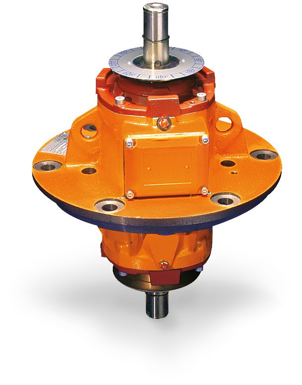
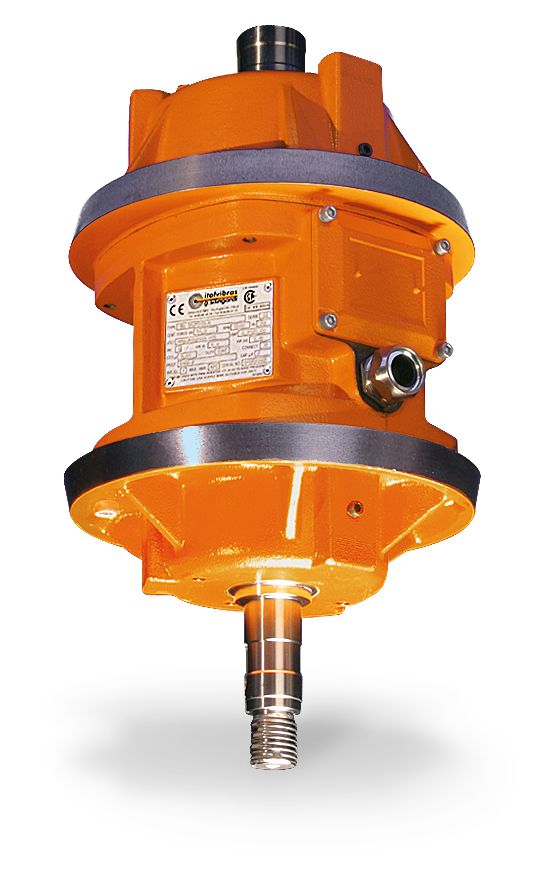
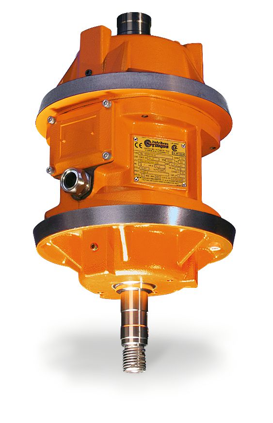
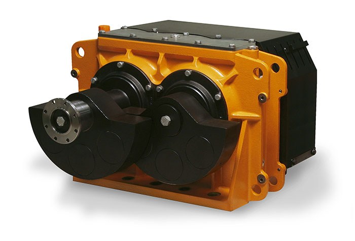
Each C type weight group (in twos) is adju-
stable by phase shifting one in respect to
the other. Each D type weight group (lamel-
lars) is adjustable by removing one or more
lamellar elements.
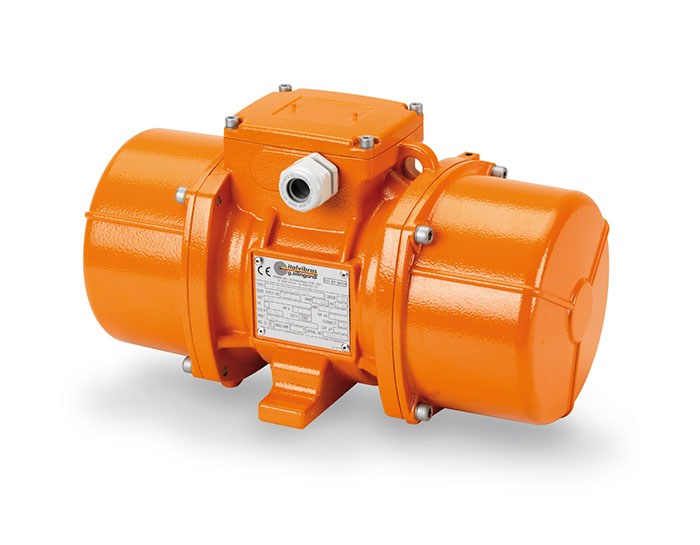
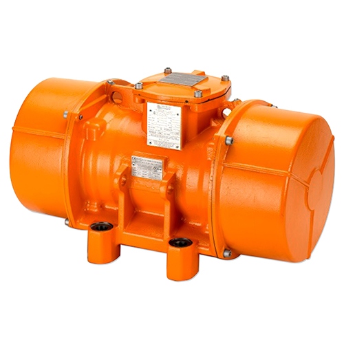
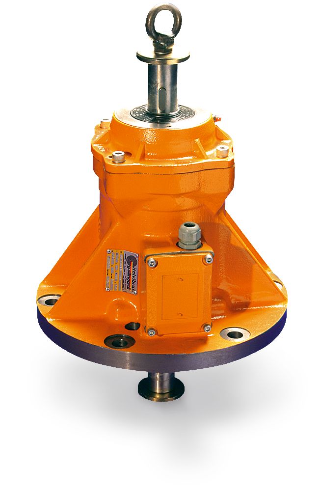
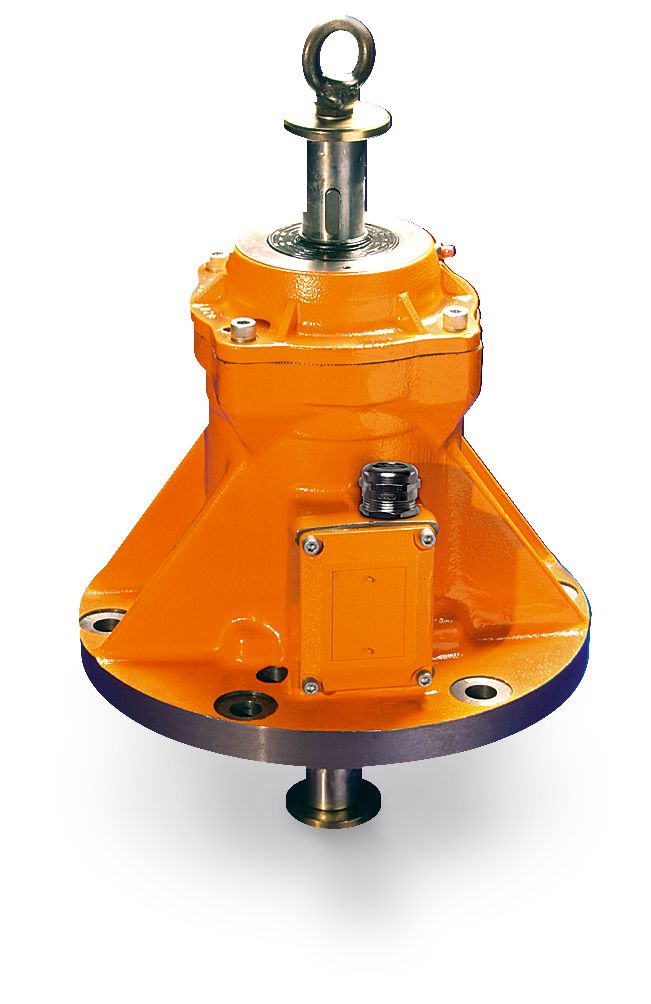
Infinitely adjustable centrifu-
gal force
Centrifugal force adjustable
from max. to min. by removing
the lamellar weights.
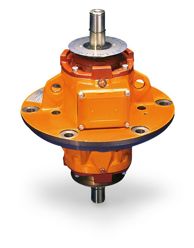
Weight adjustment:
the weights at the two ends of the shaft can be
staggered as required, with reference to the graduated discs on the
shaft itself.
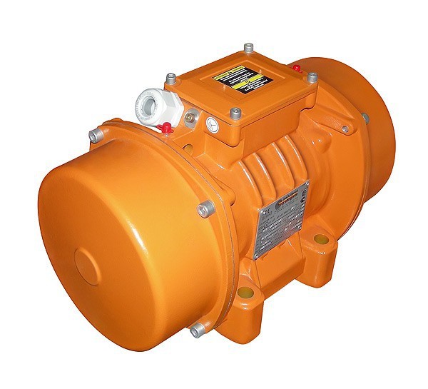
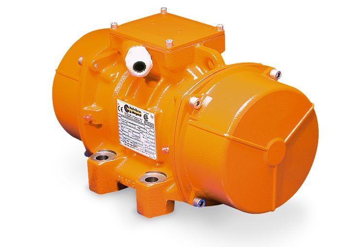
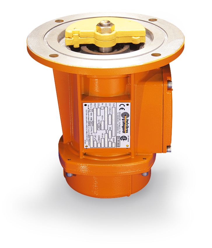
Type “C”
Type “D”
Type
Dimensional specifications (mm)
Holes
Cable entry
thread
Fig.
A
øB
øC
øD
øH
N°
E
F
G
I°
L
M
øN
Type
Dimensional specifications (mm)
Holes
Cable entry
thread
Fig.
A
øB
øC
øD
øH
N°
E
F
G
øI
L
M
Fig. I
Fig. L