ITALVIBRAS
58
H
B
N
600411
MVCC 3/100-MF
3000
12.0
120
1.19
5.0
100
8.0
4.0
MB
600428
MVCC 3/200-MF
3000
21.0
211
2.07
6.0
190
16.0
8.0
MB
600469
MVCC 3/500
3000
49.9
503
4.93
13.1
270
22.5
11.3
A
600405
MVCC 3/1200
3600
78.0
1130
11.1
20.8
530
-
22.0
A
600464
MVCC 3/1500
3600
105
1520
14.9
21.5
530
-
22.0
A
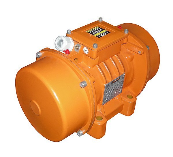
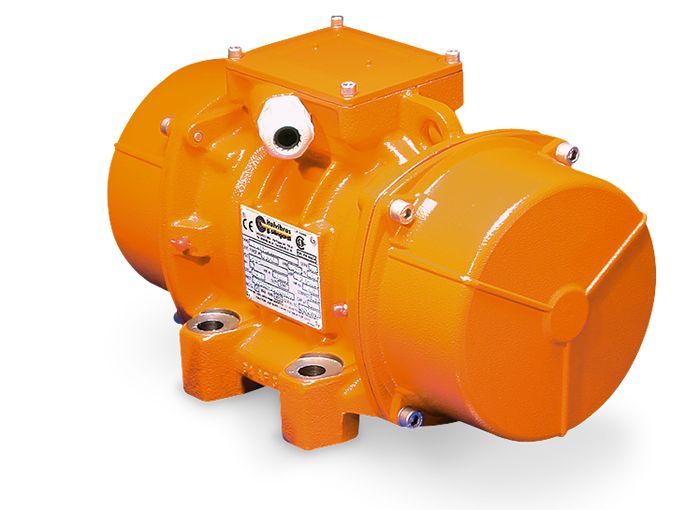
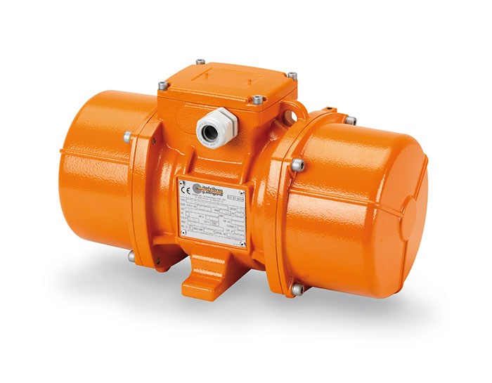
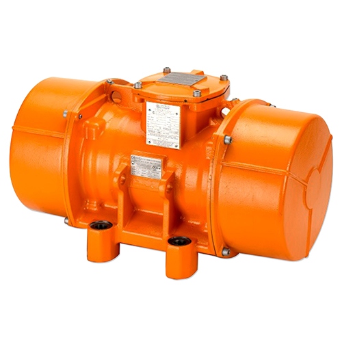
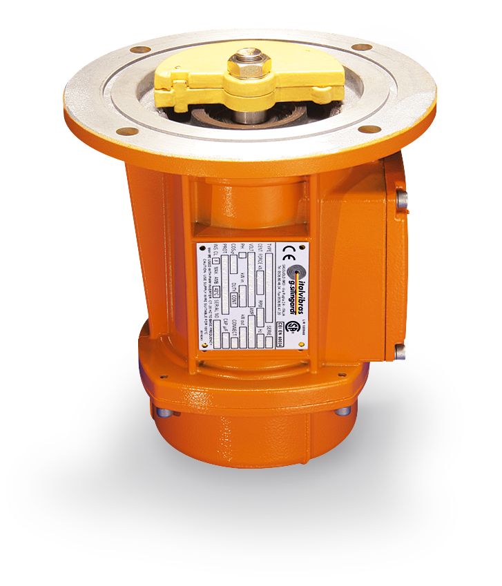
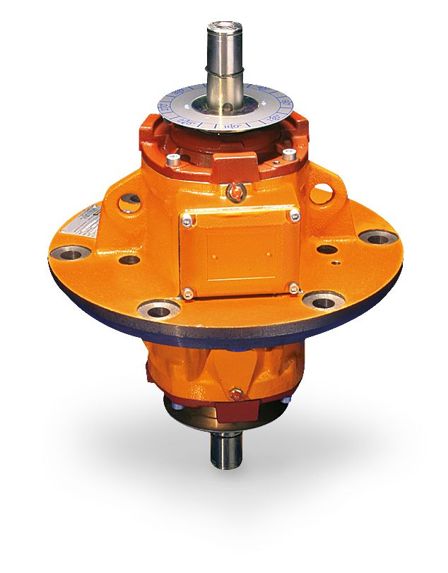
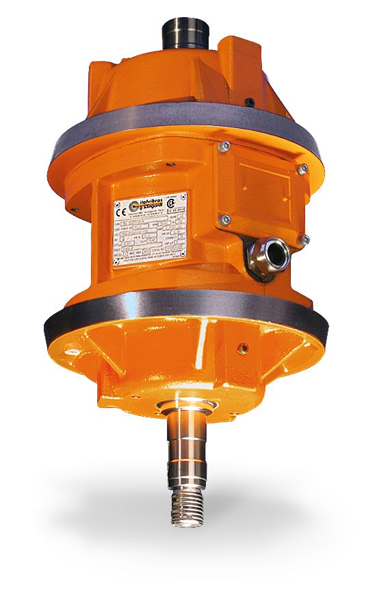
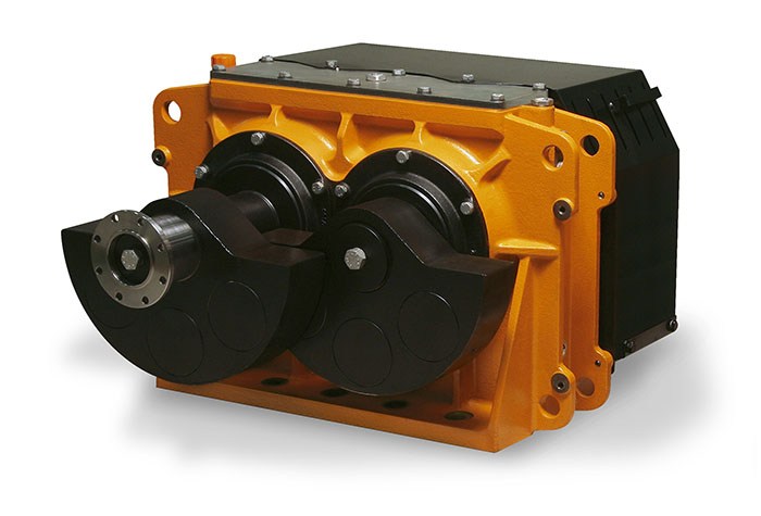
MVCC
The MVCC series of vibrators in direct current has been de-
signed for use in those situations where network electricity
is not present. In particular for hoppers, silos and gate-con-
trols and roll-on roll-off vehicles (concrete mixers, pumps
for concrete, plasterers, salt distributors, gravel spreader,
fertiliser spreader, hauled silos, industrial sweeper filters).
The newly-conceived electric motor, with permanent ma-
gnet poles, and the increase in size of the electrical parts,
allow constant, high yielding performance.
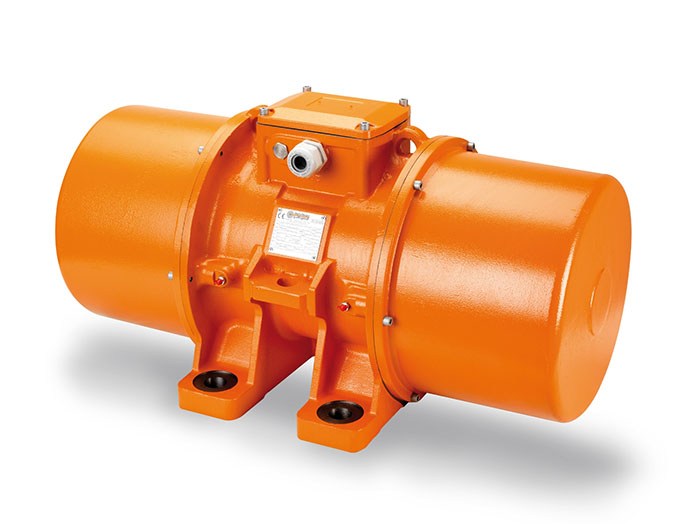
The MF models have a multi-hole fixing base to adapt to
different centre distances of drilling.
Technical features
Power supply
In direct current at 12 or 24V.
Conformity with European Directives
Electromagnetic compatibility 2004/108/
EC.
Functioning
Continual service (S1) at maximum decla-
red centrifugal force and electric power.
Intermittent services are also possible
depending on the type of vibrator and
our operating conditions.
For detailed information contact our
technical assistance office.
Centrifugal force
Range extended up to 1520 Kgf. (14,9 KN),
with centrifugal force adjustable from 0
to 100%.
Mechanical protection
IP 66 according to IEC 529, EN 60529.
Protection against mechanical impacts
IK 08 according to IEC 68, EN 50102.
Ambient temperature
From -20°C to +40°C.
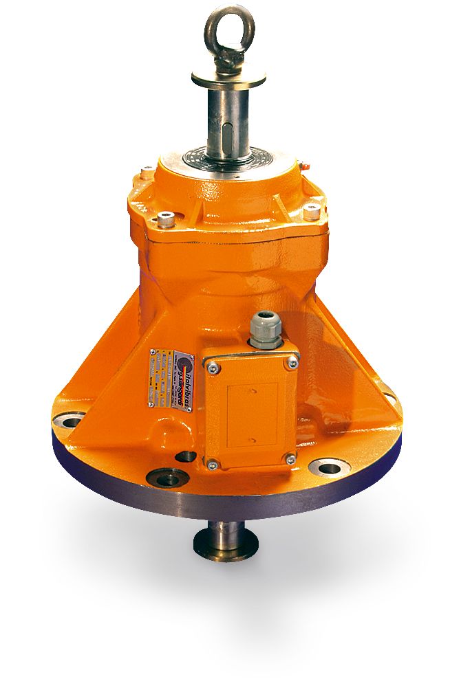
Fixing of the vibrator
In all positions and therefore without
restriction.
Lubrication
Sealed ball bearings, lubricated “for life”.
Terminal box
On MF models it’s positioned underne-
ath the vibrator, on the same side as the
fixing base.
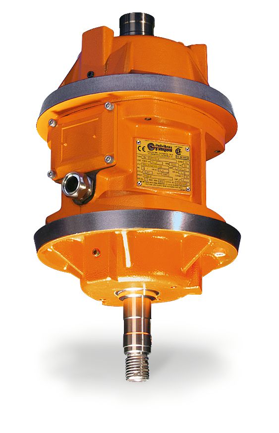
Electric motor
Direct current with permanent magnet
poles. The rotor is a wound brush-type
with collector.
Casing
In high-tensile aluminium alloy.
Bearing flange
Constructed in aluminium with steel
bearing seat. The geometry of the flange
transmits the load to the casing uni-
formly.
Motor shaft
In treated steel alloy (Isothermic harde-
ning) resistant to stress.
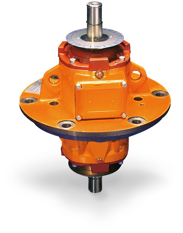
Eccentric weights
Enable continuous adjustment of the
centrifugal force. This adjustment is facili-
tated by a graduated scale that expresses
the maximum centrifugal force. A pa-
tented system (patent N°MO98A000194)
called ARS prevents adjustment errors.
Weight covers
In alluminum alloy for models 3/100-MF,
3/200-MF and 3/500; in AISI 304 stainless
steel for models 3/1200 and 3/1500.
Description
Code
Type
Mechanical specifications
rpm
Static
moment*
kgmm
Centrifugal force
kg
kN
Weight
kg
Electrical specifications
Max input
power
W
12 V
24 V
Max. current
A
* Working moment = 2 x static moment.
Fig.
Direct
current