CHIARAVALLI


144
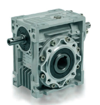
HOW TO SELECT THE CORRECT RIGHT-ANGLE
HOW TO SELECT THE CORRECT RIGHT-ANGLE BEVEL GEAR
TECHNICAL NOTES
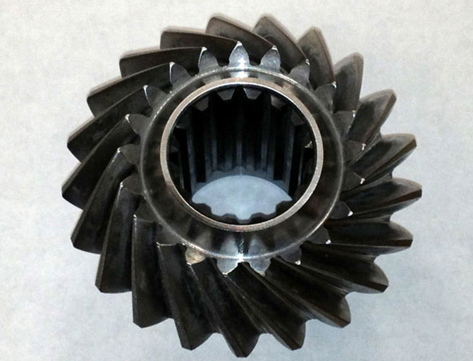
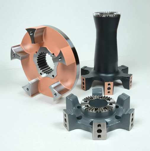
Selecting the correct type of angle bevel gear is not simply a question of defining the power
required in relation to R.P.M. and the torque to be transmitted. If also involves defining the
conditions under wich the angle bevel gear will be used. Defining operating conditions
involves taking into consideration a number of factor such as the type of operating cycle
(intermittent, continuous), radial and axial loads on the shaft ends, maximum and minimum
temperatures, ambient conditions (e.g. dust and dirt levels) and the type of lubricant used. To
decide the type and size of angle bevel gear required, proceed as follows.
1) Use table 2 to define the Service Factor for your application.
2) Calculate the Rated Power (Pn); Pn = Pe (Horsepower) x FS.
3) Use the output speed and the rated power (Pn) to select the angle gear size and
transmission ratio required for your application.
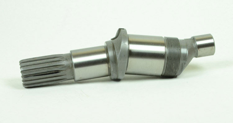
4) Check that the radial and axial load at the midpoint of the exposed shaft end does not
exceed the values shown in table 1.
5) Check that the operating temperature does not exceed -20°C ÷ 80°C
6) If you require a 1/2 or 1/3 ratio, do not use a speed multiplier with an input more than 750
R.P.M.and 500 R.P.M. in ratio 1/2 and 1/3, respectively.
7) If the unit is to be used in very dusty conditions, protect the oil seal against direct exposure
to dust to prevent abrasive damage which might shorten the working life of the unit.
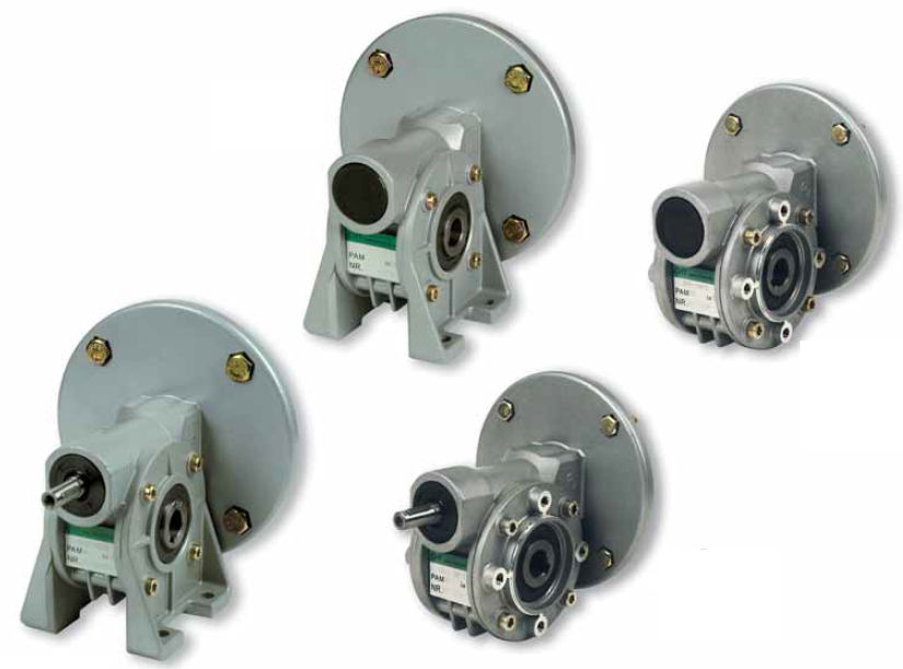
MAX RADIAL AND AXIAL LOADS
SIZE
MAX AXIAL LOAD IN Kg.
MAX RADIAL LOAD IN Kg.
RB1
1
1
1
2
RB2
0
2
1
4
RB3
3
4
6
7
RB4
9
4
8
8
RP1
5
1
8
2
RP2-3/4
0
3
3
5
RP5-6
5
4
5
6
RP7
0
6
0
8
TABLE 1
SERVICE FACTOR Fs
3
8
12
24
0.7
0.9
1
1.3
0.9
1
1.3
1.8
1.3
1.6
1.8
2.3
uniform load
load with
moderate shocks
load with shocks
hours of operation for day
TABLE 2