COMINTEC


40
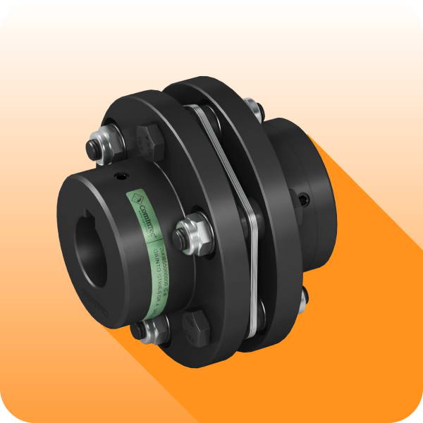
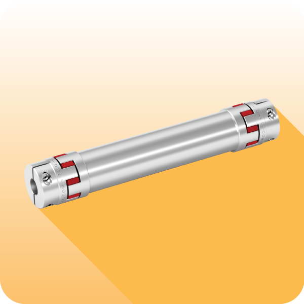
... + GSF - model with bellows coupling: technical data
Size
D3
Dk3
E3 H7
N3
P3
A
F
D H7
R
R1
W
SG
GSF
min.
max.
00.40
1
34
36
5
16
17
16,5
44
38
12
72
84
48
00.47
2
40
44
8
20
20,5
21
50
42
17
87,5
102,5
58
0.63
3
55
58
10
30
22,5
27
70
62
20
107,5
124
68,5
1.80
4
65
73
14
38
26
32
85
75
25
126
144
81
2.96
5
83
89
14
45
31
41
100
82
35
155
173,5
102
TECHNICAL DETAILS
TRANSMITTABLE TORQUE WITH LOCKING ASSEMBLY
DIMENSIONS
Size
Torque
[Nm]
Weight
[Kg]
Iner
Ɵ
a
[Kgm
2
]
Max
speed
[Rpm]
Screws
S2
Tightening torque
Misalignments
Rigidity
SG
GSF
Nom
Max
Grubscr. (S2)
[Nm]
Screws (S2)
[Nm]
Angular
α
[ ° ]
Axial
X
[mm]
Radial
K
[mm]
Torsional
R
T
[Nm/rad • 10
3
]
Axial
R
A
[N/mm]
Radial
R
R
[N/mm]
00.40
00
5
10
0,07
0,000024
4000
M4
M3
2,9
0,8
1° 30’
±0,5
0,20
3,050
30
92
00.47
0
15
30
0,14
0,000050
4000
M5
M3
6
0,8
1° 30’
±0,6
0,20
7,000
45
129
0.63
1
35
70
0,29
0,000229
4000
M6
M4
10
2
2°
±0,8
0,25
16,300
69
160
1.80
2
65
130
0,45
0,000622
3000
M8
M4
25
2
2°
±0,8
0,25
33,000
74
227
2.96
3
150
300
0,93
0,000834
2500
M10
M4
49
2
2°
±1,0
0,30
64,100
87
480
Size
Transmission torque
[Nm]
according to the ø finished bore
[mm]
5
6
7
8
9
10
11
12
14
15
16
18
19
20
24
25
28
30
32
35
38
40
42
45
1
5
6
7
8
9
10
11
12
14
15
16
2
13
14
15
18
19
22
24
25
29
30
32
3
25
27
32
34
36
41
43
45
54
57
63
68
4
75
79
83
100
104
116
124
133
145
158
5
132
158
165
183
198
211
231
248
263
277
295
NOTES
• These details refer only for the coupling (GSF), for torque limiters details see on page 34-37.
• Weights are relevant only to the pilot bore (GSF); iner
Ɵ
as refer only the coupling with maximum bore (GSF).
• Microswitches EM1 or EM2 and induc
Ɵ
ve sensor PRX see page 73
Grubscrews
S1