BALDOR


266
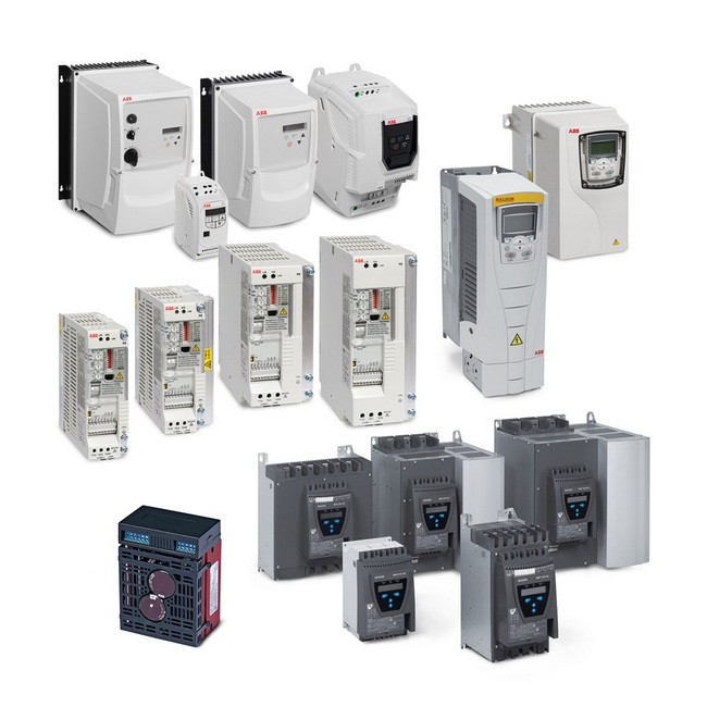
Soft Starters & Dynamic Brakes
Farm Duty
Motors
Definite Purpose
Motors
Unit Handling Motors
Brake Motors
200 & 575 Volt
Motors
IEC Frame
Motors
50 Hertz
Motors
Inverter/Vector
Motors & Controls
DC Motors
and Controls
Soft Start &
Dynamic Brakes
Multipurpose
Dynamic Brake
5-500 HP
208-460V 50/60 Hz
5-600 HP
230-575V 50/60 Hz
Applications:
Stopping coasting loads such as chippers, saws, cutting tools
and conveyors. It can also be used to stop windmilling fans before starting.
Features:
The Multipurpose Brake is a microprocessor based solid state
brake designed to eliminate the problems common to traditional DC injection
brakes. To eliminate blown fuses and welded contacts, the microprocessor
senses when AC is no longer present before turning “on” the braking. A faster
zero speed sensing circuit turns off the braking as soon as the motor stops to
reduce motor heating.
Model
Number
208/230/460 VAC 50-60 Hz.
(a)
BQ7-016-CP
BQ7-030-CP
BQ7-055-CP
BQ7-080-CP
BQ7-135-CP
BQ7-160-CP
BQ7-250-CP
BQ7-420-CP
BQ7-600-CP
230/460/575 VAC 50-60 Hz.
(a)
BQ8-016-CP
BQ8-030-CP
BQ8-055-CP
BQ8-080-CP
BQ8-135-CP
BQ8-160-CP
BQ8-250-CP
BQ8-420-CP
BQ8-600-CP
Output
RatIngs
Hp Rating
230 VAC
5
10
20
30
50
60
100
150
250
460 VAC
10
20
40
60
100
125
200
350
500
575 VAC
10
30
50
75
125
150
250
400
600
Current Rating
16
30
55
80
135
160
250
420
600
Derate
Above 1000m (3300 Ft.) decrease amp rating 1% for each additional 100m (330 ft.)
Above 45° (115°F) decrease amp rating 1.5% for additional °C (0.84%/°F)
±nput
RatIng
Frequency
50-60 Hz. ³5%
Voltage
control board 115 VAC +10% to -15%
Phase
Three Phase
Control
Spec.
Control Type
Microprocessor Based
Control Method
Common Anode SCR and diode to achieve DC
Control Power
External control transformer (suppled with certain models) 115 VAC 50-60 Hz. to the control board
Power Consumption
1.5 VA by the control board
Operating Modes
Master mode (brake controls starting and stopping of motor)
Prestop mode (prestop a windmilling load)
Basic mode (for replacement of existing dynamic brake)
Brake Timer Ranges
1-17 seconds; 15-32 seconds; 30-47 seconds; 45-62 seconds
Zero Speed Sensor
Selectable (brake disengages when motor stops rotating)
M Contact Rating
10 amp at 125 VAC
Brake Magnitudes
Two adjustable brake magnitudes
Status LEDs
Power/Ready/Run/Braking
Peak Inverse Voltage
460 VAC controls - 1200V; 575 VAC controls - 1600V
Heat Loss
1 watt per amp while braking
DIagnostIcs
Error Indicators
Improper line voltages; Motor contactor failed to open; Brake contactor failed to open; Improper line frequency
DImensIons
Height x Width x Depth
14.75” x 12.88” x 5”
14.75” x 12.88” x 6”
21” x 21” x 8”
33” x 33” x 9.75”
AmbIent
CondItIons
Temperature
Enclosed 0-45°C (32° to 113°F) open/panel 0 to 50°C (32° to 122°F)
Design Specifications
• Microprocessor based control
• SCR/Diode power circuit
• Line contactor
• Motor voltage sensing circuit
• Zero speed sensing
• Four braking time ranges
• Three operating modes
• Two adjustable braking
magnitude potentiometers
Environmental and
Operating Conditions
• 40 degrees C
• 1000 feet elevation
• Open panel design
• 208, 230, 460, 575 volt input line
voltage
• 50/60 Hz input frequency
• Control voltage 120 VAC
Protective Features
• Shorted SCR protection
• Motor terminal voltage sensing
• Time delay to allow motor flux to
collapse
• Motor starter interlock contact
(a)
For 50 Hz. applications use the brakes without a transformer and supply a separate 115 VAC supply to the brake control board and contactor.
The brake can also be ordered as a BQ9 - XXX - XX for 380/400/415 VAC applications. It will have the control transformer mounted on the panel.