COMINTEC


54
+
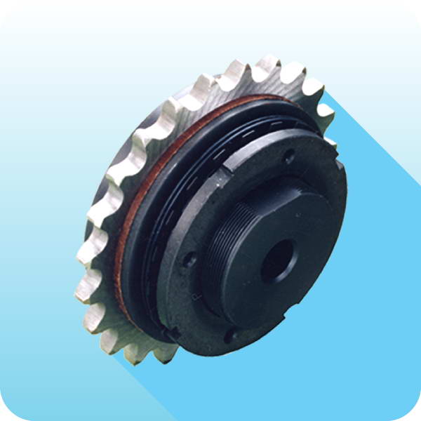
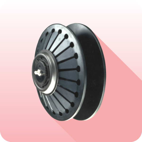
DSM - modular torque limiters (free rota
Ɵ
on) : addi
Ɵ
onal informa
Ɵ
on
This model of freely rota
Ɵ
ng limiter DSM has been speci
fi
cally designed to protect against overload in heavy industry machines with
signi
fi
cant powers and iner
Ɵ
a and high speed of rota
Ɵ
on.
The seals present protect from dust, dirt and prevent leakage of grease used within.
In nominal opera
Ɵ
ng condi
Ɵ
ons the transmission torque is transferred from the driving to driven components by a di
ff
erent number of
modules assembled symmetrically on an outer circumference of the device with the possibility of di
ff
erent con
fi
gura
Ɵ
ons of springs inside
them.
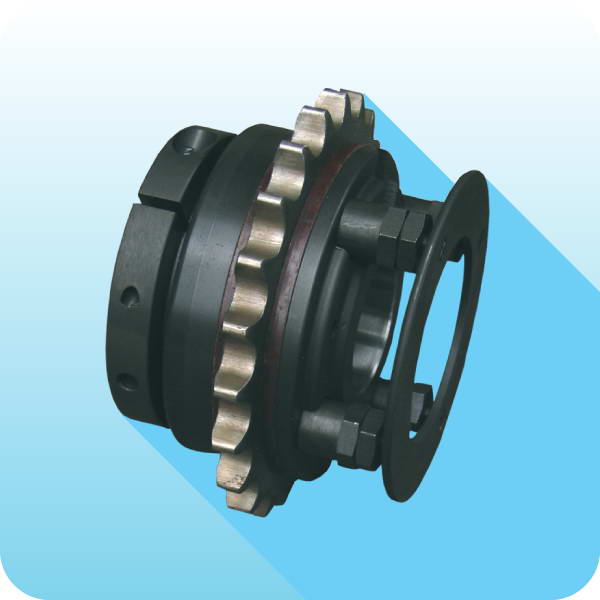
In case of overload, when the torque demand from the driven por
Ɵ
on exceeds that of calibra
Ɵ
on, the balls will be forced out of the seat
area and by doing so axially move the central pistons within the modules. This release occurs instantaneously separa
Ɵ
ng the driver and
driven sec
Ɵ
ons allowing free rota
Ɵ
on of the sec
Ɵ
on s
Ɵ
ll rota
Ɵ
ng un
Ɵ
l the transmission is stopped.
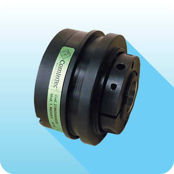
The device can also be equipped with a overload detec
Ɵ
on ring (DSM/SI), connected to the central pivots of the various modules, to be able
to “read”, through an electromechanical switch (model ComInTec: EM1) or an induc
Ɵ
ve sensor (model ComInTec: PRX), the axial movement
and send an electrical signal to trigger an alarm and stop the transmission.
The re-engagement of the individual modules must be done with the machine stopped as described in the previous sec
Ɵ
on devoted to it.
OPERATION
ORDER EXAMPLE
MODULAR TORQUE LIMITER
Size
Model
No. of modules
Finished bore
Torque
0
DSM
6 modules
ø50 H7
1000 Nm
The device comes complete with
fi
nished bore, unless otherwise noted, with tolerance H7 and keyway DIN6885-1 with H9 tolerance.
The
fi
xing of the device can be made axially through the bore with a washer or on request an internal locking assembly.
The device is NOT self-suppor
Ɵ
ng so it is necessary to provide ensure that the sha
Ō
on which the device will be mounted are supported
with bearings and in the case of sha
Ō
to sha
Ō
connec
Ɵ
on the misalignment values detailed in the catalogue are noted.
HOW TO USE AND ASSEMBLE
These devices, are maintenance-free.
In the case of the torque calibra
Ɵ
on it is important to take into account several variables that combined together can a
ff
ect the dura
Ɵ
on of
the limiter:
Torque value of interven
Ɵ
on in rela
Ɵ
on to the actual range of the limiter.
The frequency and dura
Ɵ
on of interven
Ɵ
ons.
Ability to dissipate the heat generated by slippage or disengagement.
Speed
of rota
Ɵ
on.
Environmental condi
Ɵ
ons at work.
MAINTENANCE
Size
from 0 to 2
No. of modules
3 MD
6 MD
9 MD
COUPLING
Model
Elas
Ɵ
c element
Finished bore
Hub type
GAS
Normal red element 98 Sh-A
ø110 H7
A1
Model
GAS
Jaw coupling
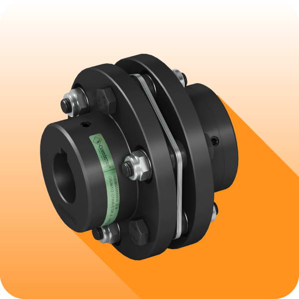
GTR
Torsionally rigid disc coupling
Locking type
See hub connec
Ɵ
on type list on page 4
DRIVE ELEMENT
Descrip
Ɵ
on
Pulley GT 14M-37 Z=72
Model
DSM
DSM/SI