COMINTEC


53
t
c
d
r
u
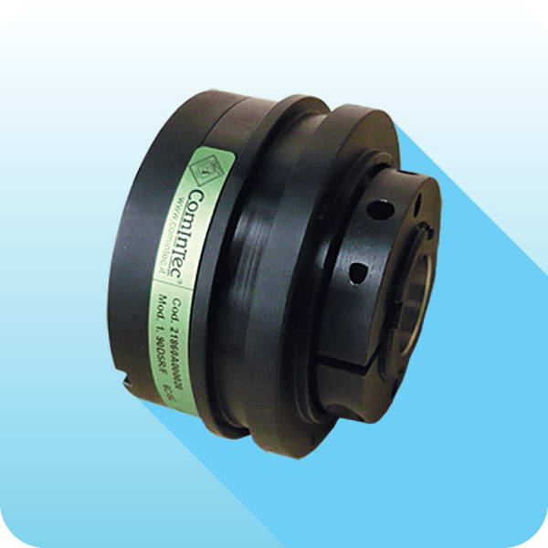
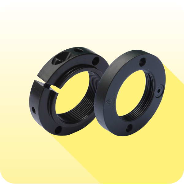
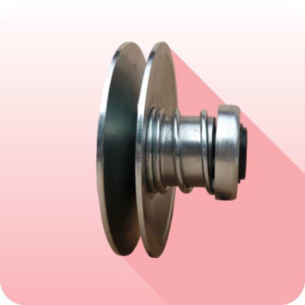
Made in steel fully turned with high mechanical resistance.
Ease of registra
Ɵ
on.
Ease of manual re-engagement.
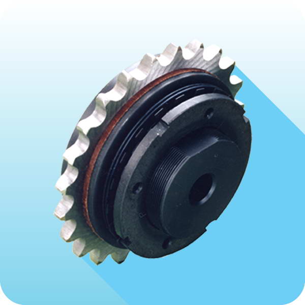
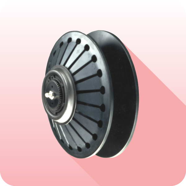
Mounted on DSM devices for a torsionally rigid transmission.
Disengaging with complete detachment between the driving and driven side.
Available in two sizes.
MD - module of calibra
Ɵ
on: technical data
DIMENSIONS
The key elements of the DSM module consist of the central piston (p) that will drive a hardened ball (s) into the loca
Ɵ
on seat (t).
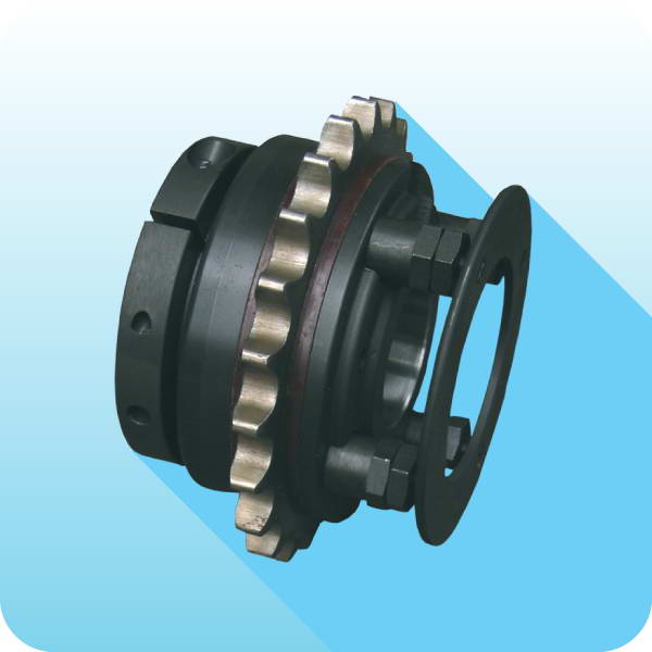
Torque adjustment can be made also whilst the module is
fi
Ʃ
ed to the torque limiter by the rota
Ɵ
on of the hexagonal adjuster nut (r).
Make sure that during the adjustment the
fi
xing screw (u) is fully unscrewed to allow free rota
Ɵ
on of the adjuster nut. The units are
supplied as standard with the minimum possible torque se
ƫ
ng but by rota
Ɵ
ng the adjuster nut clockwise the torque value will increase,
and the se
ƫ
ng can be monitored by viewing the adjustment notches located on the circumference of the adjuster nut. A complete
revolu
Ɵ
on of the adjuster nut will equal one pitch. It is important once se
ƫ
ng is completed to
Ɵ
ghten the locking screw (u) in order to lock
the adjuster nut in place. For more detailed se
ƫ
ng instruc
Ɵ
ons please see the
fi
ƫ
ng and se
ƫ
ng instruc
Ɵ
ons sheets available.
CALIBRATION
The re-engagement of the limiter is manual and should only be performed with the device at rest.
Turn the
fi
xed base (c) or the mobile base (d) so that the two reference marks are in line.
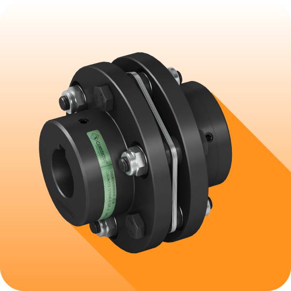
At this point, insert the pins of the related modules with slight but
fi
rm pressure using a tool or rubber mallet.
RE-ENGAGEMENT
Device engaged
Device disengaged
Re-engaging the device
u
Mark on body
Nut notches
Pitch = 1 revolu
Ɵ
on
Calibra
Ɵ
on of a module
Size
A1
B1 h7
C1
D1
E1 h7
K1
M1
U1
V1
DSM
MD
0
2
66
38
42
40
24
M5
65
5,5
3xM4
1
2
3
87
50
56
54
30
M8
95
5,5
3xM4